Author
Zigurat Global Institute of Technology
Blog / BIM & Construction Management
Categories

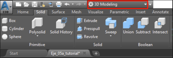 2- With the hidden terrain, we select "all" the 3D objects of the corridor and go to the Solid/ Solid Editing/ Extract Edges menu. (This action may require some time depending on the model and the PC you are using).
This way we will obtain all the lines that made up our corridor. After this process, they have ceased to be 3D Objects and can be used and manipulated.
At this time we are prepared to create our surface.
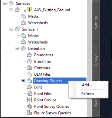 4- In the pop-up menu, we select lines and accept. Next, we select "all lines" of our corridor and press Enter.
5- We select as surface style: 2D Triangles (Keep in mind that as it is in 2D we must have selected the top view to be able to visualize them).
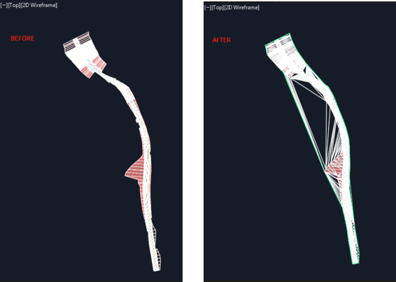
At this time, and generally, creating the surface in Civil 3D creates triangles that should not exist. We must "clean" the surface by eliminating said triangles so that it fits into our corridor.
Below we can see the corridor before and after creating the surface:
 6- We can perform the elimination of the remaining triangles in two different ways:
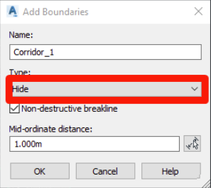
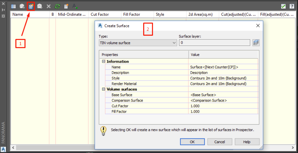 We click on 1 and in the pop-up window (2) we use:
As Base Surface: The terrain provided
Comparison Surface: The created surface
We configure the rest of the options and we see the resulting cuttings, filling and calculation of earthworks.
 4- In the lower bar it asks us to select object or Surface: Press S to select surface. We select the surface created in the section.
5- We follow the steps of point 2 of this section and select the surface created in section 3.
 From here we can extract that between the first and second method no significant changes are appreciated in the scope of a large-scale work. However, in the third method, we perceive a remarkable difference that should not exist since it comes from the same model. From this, we can conclude that there is some type of failure in the IFC from Autodesk Civil 3D or a misinterpretation of the volume parameter of slopes and embankments.
In addition, it has also been proven that Naviswork is not able to obtain the data related to the measurement based on the IFC provided.
Note: At any time reference is made to a specific case, it can not be extrapolated to any IFC format file. This should be one of the correct formats to be able to make measurements. Hence the importance of the IFC being a true reflection of the original model.
In any case, it is estimated that the designer/modeler must provide the model prepared to take the measurements correctly and without misunderstandings. In the case of providing an IFC, it must be correctly configured and checked for its agreement with the original model.

Zigurat Global Institute of Technology