In the following article, framed within the International Master’s in HVAC with Energy Efficiency, we are going to analyse concepts related to hydraulic circuits in HVAC installations, as well as the pumps commonly used in heating and cooling installations.
These latter operate many hours per year and, in many cases, run at constant rotational speed independently of the energy demand of the installation. Therefore, if we adopt measures so that the pumps in the circuits operate at variable flow rate, we will be contributing directly to energy savings.
Indeed, energy savings in closed hydraulic circuits will depend on the operation of the pump, the control valves and the balancing valves. Focusing on the operation of pumps (commonly known as circulator pumps), in HVAC hydraulic circuits the pumping energy consumption can be considerably reduced if the HVAC installation operates at variable flow rate.
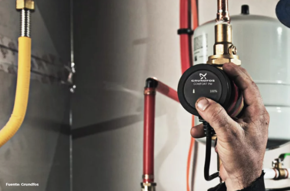
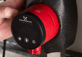
Circulation pump - Source: Grundfos
In a building with air conditioning (HVAC), the heating and/or cooling demands are in a state of continuous change. This depends on several factors, such as external climatic changes (annual seasonal changes) or the internal conditions of the conditioned spaces (temperature, internal load, etc.). Installations are designed to operate at full load; however, installations operate most of the time at partial loads. Therefore, it is interesting to analyse the behaviour of pumps as the energy demand of the installation decreases or as the generation equipment reduces its operation. The possibilities of HVAC installations operating at variable flow rate are as follows:
Constant pump speed
Variable speed with Δp = constant
Variable speed with Δp = variable
Variable speed controlled by load
In this discussion we are going to focus on analysing the second and third option, variable speed with Δp = constant and with Δp = variable. In the design phase, different strategies can be used to reduce pressure losses, establishing good practice criteria that limit pressure losses (pressure losses in pipes below 20 mm water column per metre, use of straight-through valves with almost zero pressure loss, etc.). When it comes to saving energy in hydraulic circuits, the first optimisation of pumping energy consumption must begin in its design at nominal load (depending on the use of pumps at variable or constant speed). Subsequently, it will aim to reduce its energy consumption by reducing the circulation flow rate at partial loads of the installation. The problem in many HVAC installations is not that the pressure loss of the hydraulic circuit is high, but that a pump larger than necessary has been installed. Pump oversizing is a common practice and the problem lies in the fact that HVAC installations are often not prepared so that the necessary adjustments are carried out during commissioning or maintenance operations. It becomes essential to install flow meters that indicate the circulating flow with certain precision, which could well be 5%–10%, but which will allow the flow to be adjusted by the maintenance personnel. Flow adjustment can be carried out using three techniques:
Flow throttling by a valve in series. The energy consumption of the pump will decrease very little. Regulation valves at the pump discharge are something to eliminate from installations..
Pump replacement, impeller replacement or impeller trimming. This is the most efficient regulation system in the case of circuits that are going to operate at constant flow. Flow adjustment will be carried out with a significant reduction in energy consumption.
Variation of rotational speed. This is a simple and economical method, at least in pumps below 2 kW. A simple adjustment of the flow is achieved that can also be reversible. In constant-flow circuits, losses in the frequency drive will be assumed that in principle should not exist.
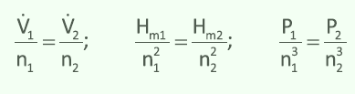
Although we are not going to dwell on explaining in detail the operating principle of variable-speed pumps, we could state that when a pump only changes its rotational speed (same pump diameter) the following condition is fulfilled:
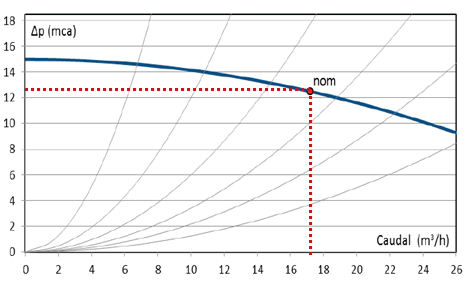
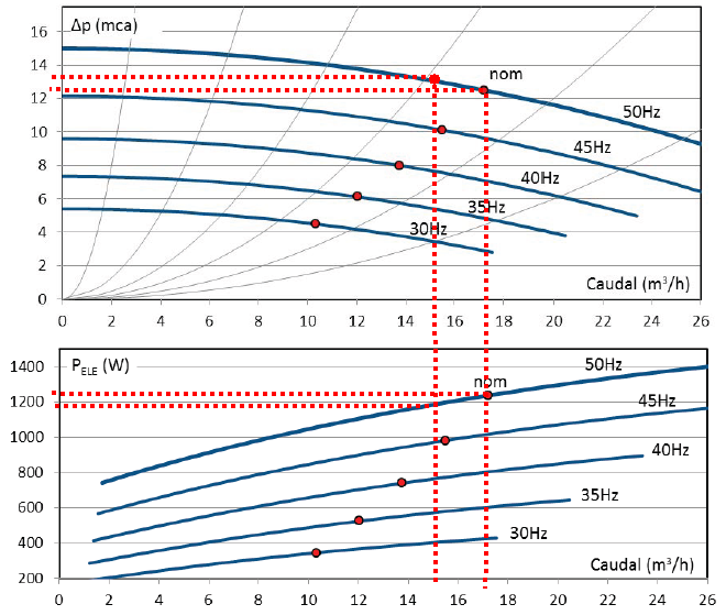
Applying the previous equivalence expression, operating points of a pump can be taken and their homologous points determined at other rotational speeds. For example, let us suppose that we have a pump in which the nominal flow rate and the head it must overcome are known. These data are as follows:
Nominal flow rate = 17,2 m3/h
Head = 12.5 m w.c.
Pump design point
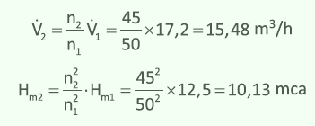
For the nominal flow and head conditions above, if a frequency inverter is installed in the pump so that its frequency changes from 50 to 45 Hz, the homologous point will be:
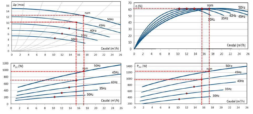
In the following image we observe how the different parameters that represent the characteristic curves of a pump vary when working at different frequencies:
Characteristic curves of a pump at different frequencies (upper left corner)
The efficiency of two homologous points is equal at different rotational speeds (or frequencies), only the flow changes (upper right corner)
Power curve on the pump shaft at different frequencies (lower left corner)
Electrical power curve consumed by the pump at different frequencies (lower right corner)
Parameters of a pump's characteristic curve
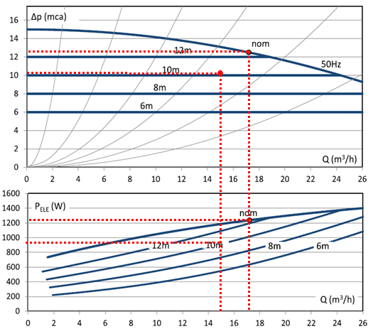
For the case of variable-speed pumps operating at constant differential pressure (Δp = constant), the system is adjusted in such a way that the pump varies its rotational speed to maintain the delivered head (pressure) constant. The pump is equipped with a differential pressure sensor and the frequency inverter is programmed to maintain this constant.
During the commissioning of the HVAC installation, the technician can configure the pump working head to the value considered most appropriate.
Pump at variable speed operating at constant differential pressure, Δp = constant
In a variable-flow circuit, first the pump will be adjusted for the nominal (maximum) flow situation. At this point the control system is indicated to maintain the delivered head constant. As the water flow demanded by the system decreases (as system control valves close: radiators, fan coils, cooling/heating coils, etc.), the pump will maintain the head equivalent to the reduction in supply flow, obtaining the following advantages:
The flow decreases significantly, reducing the velocity in the pipes and possible noise problems due to excess flow.
The energy consumed decreases significantly in systems where demand is highly variable (high number of hours of the system operating in this variable-demand mode).
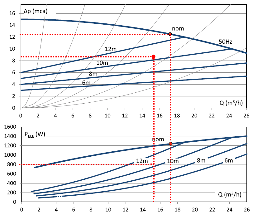
For the case of variable-speed pumps operating at variable differential pressure (Δp = variable), this is a modification of the previous system. In recirculation circuits, the hydraulic resistance of the circuit increases as the control valves of the terminal units close (radiators, fan coils, AHU coils, etc.). To mitigate this effect, as the control valves close, the flow supplied by the pump will decrease significantly in proportion to the closures, reducing the circuit resistance in a variable way.
In this mode, once the pump has been started and adjusted to the delivered head, regulation of its rotational speed is carried out automatically.
Pump at variable speed operating at variable differential pressure, Δp = variable
In any case, with any of the previous modes, significant energy savings will always be achieved if we compare it with constant-speed circulation pump systems:
Pump operating at fixed or constant speed
In conclusion, pressure increases as flow decreases, and in addition a differential pressure bypass valve is required to reduce partial pressure. Ultimately, the energy consumption of the pump in fixed-speed operating mode is higher than when the pump operates at variable speed.
Director of the Spanish editions of the Master’s in BIM Calculation and Modelling of MEP Installations and the Master’s in HVAC with Energy Efficiency at ZIGURAT Institute of Technology.