This article discusses the basics of the beneficial effect that can occur on a beam where a certain membrane effect develops.
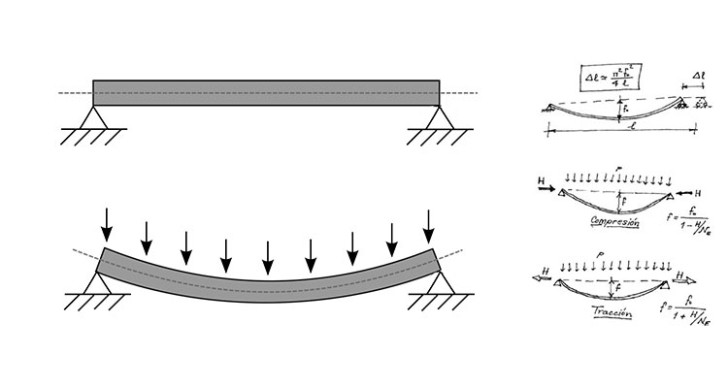
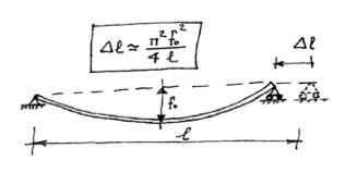
Due to the effect of the vertical load, even from its own weight, and unless the possibility of horizontal constraint exists in the supports, the fact that the piece does not change in length implies a small shift towards the center Δl.
First of all, we must keep in mind a couple of elementary concepts on the Theory of Structural Stability: 1- A transversally loaded beam experiences an increased deflection which corresponds to the load if it is simultaneously subjected to a compression axial H.
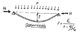
That is to say that if the transversal load is p, in the simply supported at ends beam (where one is a pinned support and the other is a roller) of inertia I and a span l, flexure produces: f0 = 5/384 pl4/E I When an axial compression of H value is given, an amplification will take place: 1/ 1- H/NE Being NE the critical load of Euler in the plane of flexion. NE = π2 E I / l2. In the case that the axil H is in tension a decrease in deflection is produced, the factor is then:
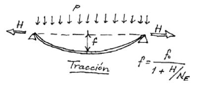 The reduction of the deflection is: 1/ 1 + H/NE
When the two supports are pinned, that is to say when they can endure horizontal reactions, it can be shown that by preventing the indicated shift a reaction appears that precisely compensates for this stretch by the action of axial. ∆M = H l / E A By equalizing and operating these shifts, a simple expression is reached, to solve by trial and error, which allows the calculation of the H reaction, depending on the parameter α = H/NE α(1+α)2 = A f02/ 4 I This has many advantages when it comes to the design of hatches, covers, sheet pavements and even dynamic behavior of steps and resistance to fire/explosions of roof purlins. It is essential that the ends resist more than the possible H force that is created by preventing the horizontal shift.
Example
Conventional approach Let's take a deck or a floor made of sheet steel S275 ,of t= 12 mm of thickness supported between bays in regular openings of light of 1500 mm. The design load is 2400 kgf/m2 ≈ 24 kN/m2, which may correspond to a live overload of accumulation, already factorized, or to an accidental overpressure. Even as a continuous beam, in its end span it would have an arrow in the middle of the span: f= pl4/ 158 E I = 25 mm and bending support M= 0.107 pl2 = 5778 mm N/mm The tension in the sheet rises to s = 6M/t2 = 240 N/mm2. In other words, of the order of 90% of the elastic limit.
Membrane option
If it is used to weld supports (slot or plug) and to apply the theory of membrane, the thickness can be reduced considerably for that same level of tension. Effectively with t=8mm, now it is in a unitary strip I= 42.66 mm4 and A=8mm, the critical load of Euler being NE= 39.29 N. The isostatic arrow with biarticulated supports is now: f0= ( 5/384) pl4/ E I = 176.5 mm The isostatic bending M0 = pl2/8 = 6750 mm N/mm The parameter a must satisfy: a(1+a)2 = A f02/ 4 I = 8 176.52 / 4 42.66 = 1460 Proceeding by trial and error we obtain a= 10.69 Therefore the real arrow is worth f= f0 /( 1+a) = 176.5 /(1+10.69) = 15 mm. It is quite inferior to that of the previous sheet. The horizontal reaction in supports H = a NE = 10.69 39.29 = 420 N The real bending is worth: M= M0 – H f = 6750 – 420 15 = 450 mm N/mm Now we have to add the bending tension and the membrane tension s = 6M/t2 + H /t = 6 450 / 82 + 420 / 8 = 42 + 53 = 95 N/mm2
Conclusion
Note that with 33% of weight reduction the tension level is of the order of 33% of the elastic limit. As a result, you save in material and gain in resistance. In plates, with their four welded edges this effect is even more advantageous. It is advisable to use the tables of part 1.7 of Eurocode 3.